Summary of Device Components
|
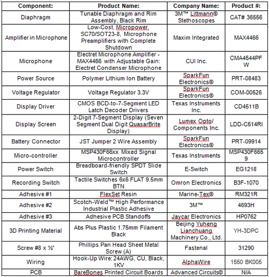
The table to the right gives each of the components required for the proposed device. In addition, for each component, the product name, company name and product number is given. The proposed case shown in the device connectivity is custom designed to fit each of these components shown to the right.
|
|
|
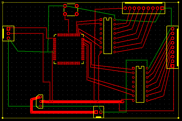
In addition, the printed circuit board design is shown to the left for the proposed device. This was generated using ExpressPCB software. This board will be approximately 4 square inches and two layers. the green lines represent ground traces and the red traces represent signal or power traces.
|
